 Back to the Contents of PARTHENON User's Manual
2. Introduction to Designing with PARTHENON
(Using a clock timer design as an example)
2.1 Description using SFL
2.2 Simulation using SECONDS
2.3 Logic Synthesis from SFL Description
2.4 How "auto.bat" works
As a way of presenting an overview of the design procedure using PARTHENON, let us first look at the concept of the design description language (SFL) and the use of the tools provided by the PARTHENON system.
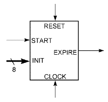
<Fig2.1> External interface of a clock timer

Let us take the design of a clock timer as an example. The clock timer is assumed to be one that outputs some kind of signal after a pre-determined number of clock pulses have been generated. To be more specific, the timer is assumed to meet the specification shown in Fig. 2.1.
- (1) When an input signal, START, is asserted (making the control signal "1" is hereafter called assertion), in other words, when it becomes effective, the 8-bit data present at the INIT terminal is fetched as the initial value. The value is decreased by one each time a clock pulse is received.
- (2) When the value reaches zero, an output EXPIRE signal is asserted and maintained until a START or RESET signal is asserted. It is assumed that START or RESET signals are asserted asynchronously (because the timing of assertion is not known).
- (3) When a RESET input signal is asserted, all actions are stopped, ready for the next START to be asserted.
Designing a clock timer as simple as the above would not require the use of PARTHENON. This simple example has been chosen only for the purpose of introducing PARTHENON. Of course, the design itself will be executed here in the same way that it would be applied to a large-scale design. (Circuits with multiple JK flip-flops cannot be designed.)

